
Whoa! That’s a lot of aluminum extrusion.
Now that I have you attention, I’ll explain what you see, where it came from, and where it’s headed (and no, it isn’t headed to engineering hell quite yet).
Description
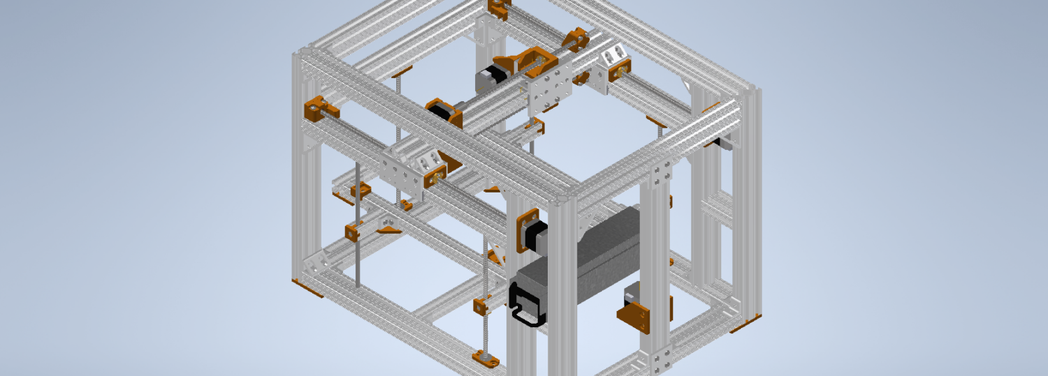
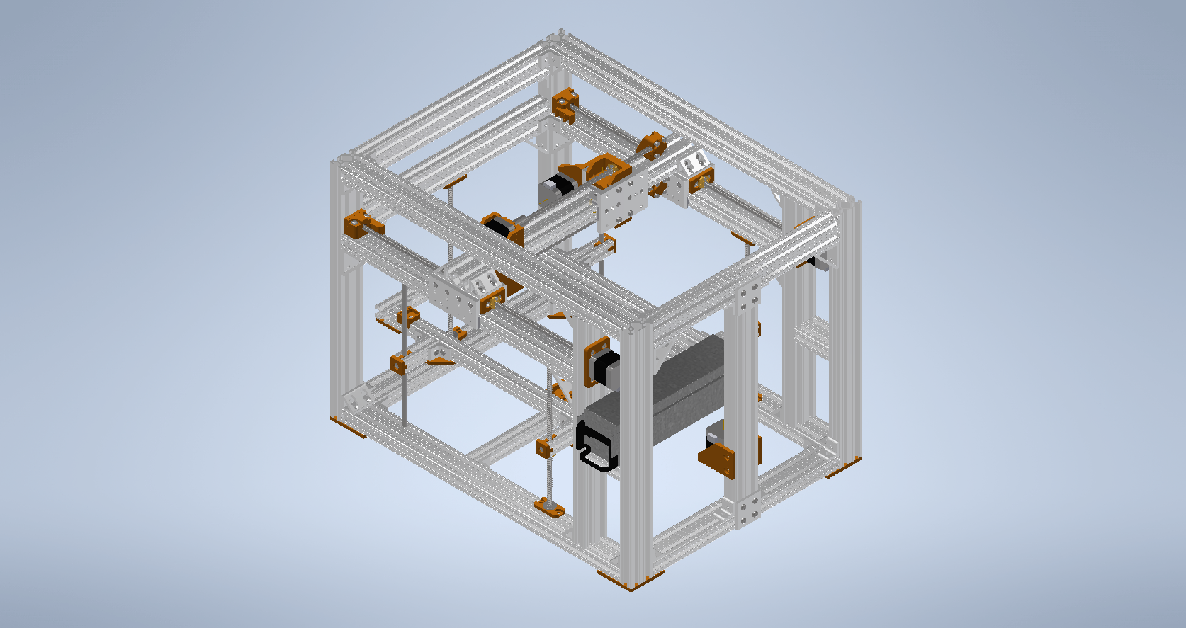
Pictured above is an incomplete rendering of the HM01 hybrid fabrication machine. It is a cartesian robot capable of additive and subtractive manufacturing operations. What does all of that mean? Let me break it down…
- Cartesian: The machine is capable of motion in three orthogonal axis. Most 3d printers and 3-axis milling machines are cartesian machines
- Additive manufacture: Any process by which an object is fabricated through the successive addition of material. The most prevalent example of this is the humble FDM 3d printer.
- Subtractive manufacture: Any process by which an object is fabricated through the successive removal of material. Instead of adding material in the shape of your part, material is removed from a larger piece of material. Lathes, laser cutters, and milling machines are common examples of subtractive manufacturing methods.
That is where the H (hybrid) in HM01 comes from. The HM01 is a hybrid system, meaning that it can can extrude material to make a part, cut away material to make a part, or both. My ultimate goal is to be able to extrude a few layers of filament, return with a milling tool to reduce the edge of the layer to a higher degree of precision, and then repeat until a relatively precise part (by 3d printing standards) is complete.
The system itself is constructed with a t-slotted aluminum frame to house the motion, power, control, and tool systems. The print bed moves in the z-axis, driven by three (almost) equidistant LEAD screws powered by a stepper motor and constrained in the transverse plane by two brass bushings riding on linear guide rods. Motion in the x-axis is provided by two stepper motors driving parallel LEAD screws to position the tool carriage. This tool carriage is otherwise free to slide along the gantry beam using sleeve bearings. Motion in the y-axis is similarly provided by two stepper motors driving parallel LEAD screws to position the gantry slides along extrusion rails. Not pictured above is the Titan aero extruder used for FDM, the variable-speed spindle and motor (still deciding on a model), heated print bed, z-axis belt, and controller board (I’m using a FYSETC S6 v1.2), as well as a few switches, pulleys, and fittings. Overall the system is 26″ x 20″ x 19.25″, has a motion box of 13.5″ x 9.1″ x 9.5″, and weighs in at over 60 lb (>27 kg). Over engineered? Probably. Future proofed with room for improvement? Definitely.
Origin
It all started at the onset of the Covid-19 lockdowns, after all the students at NC State were sent home. Away from the reactor and unable to work from home, I found myself with plenty of time to design things but none of the tools to build them. I could have bought a 3d printer, but I had always wanted to apply what I had learned repairing them and build my own. Additionally, I remained unconvinced that 3d printers could print reasonably accurate mating surfaces and was less than impressed with the strength and durability of PLA. A CNC mill was desired but I had a ‘better’ idea: why not have a machine that can do both. Obviously, it must not be an incredible idea since I had found very few examples of others on the internet doing the same, but I’m special and surely I won’t have a problem with it (so I thought). So I set out to design a cartesian machine capable of three degrees of linear motion with the ability to change tools, even mid-program.
I was aware of many of the problems I would face, especially on the firmware/software end of things, but I’ve always figured things out in the past and this time will be no different. The first image is a rendering of the design as it stands January 18th, 2021. Everything in orange was designed to be 3d-printed in university makerspaces. However, these were closed to students during the fall semester, redirecting students to 3rd-party printing services. Ironically enough, I discovered that it was more cost effective to buy a small 3d printer than to outsource their fabrication. So as classes were staring, I began to order the various hardware components necessary to assemble the machine.
Slowly, parts began to arrive from the various vendors and with the buzz and excitement of a child on Christmas, I began the process of putting together the various sub-assemblies of the system. The following are a few pictures of the sub-assemblies:
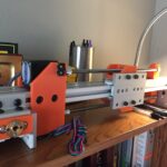
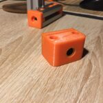
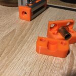

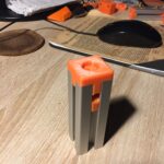

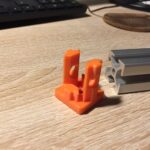

The process of fabricating all of the custom printed parts was surprisingly swift, and I found that I could often work on one part (testing, fitting, and even making design changes) while another was being printed. In this way, I was able to work twice as fast while still making headway on designing the next part. Within little over a week, I had printed half a kilogram of different parts, cleaned and fitted them, and assembled several sub-assemblies.
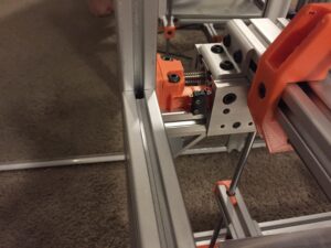
Because I was in the middle of a course on electrical engineering, I decided to wait until I had learned as much as possible before attempting to set up the power and control systems. In the mean time, I continued to chug away at completing the mechanical assembly of the machine to ensure fit and range of motion. At the time of writing this, most of the structural fittings and fixtures are completed and installed. Remaining are the mounts for the power and control systems, cutting tool, print bed, and smaller things like chip beds and side panels. The cutting tool plate will be mounted to the wide face of the tool carriage. However, deciding on a spindle-motor combination as well as its VFD supply must occur before the mounts and fixtures can be designed. As of now, the as-built assembly can be seen in the following pictures:


Where to Next
Moving forwards, most of my effort will be focused on integrating the power, control, and motion systems. This will involve fabricating the electrical housings and PSU support structure, adjusting and modifying the firmware used to work with the particular machine, and plugging it all together, all without damaging the sensitive control drivers. As said before, a suitable (and affordable) mini mill spindle and motor will need to be selected and sourced in order to spec the power requirements and figure out how much power is needed. All this will probably take longer, as classes are back in session at NC State. For my part, I hope to write again soon with news of progress on this unorthodox project.
Until next time,
Austin Wells