
When I was in high school, my friend and I were restoring a broken 3d printer because of a challenge our teacher had issued. Because it was clear that we would need some sort of benchmark(s) to check between adjustments, the two of us came up with a low and high tolerance test. My high tolerance test part was a ball bearing race, which would use standard 6mm airsoft bb’s for balls. After a full semester of scouring the internet and researching what makes a printer work well, we restored the printer and printed off one copy of my bearing design. After seeing just how poorly our printer was capable of performing, my hopes were not exactly high. Much to our surprise, however, the bb’s snapped into the race and the bearing did in fact rotate, albeit with some persuasion. The printer, while rickety and very finicky, could be pushed to produce a sufficient surface finish for pellets to roll along the track.
Fast forward three years and my younger brother related that our drafting teacher had shown his Engineering III class a ‘weird part, with little green balls inside of it’. He wasn’t sure what it was and wanting my opinion, showed me a picture of it. To my surprise, it was indeed that same crude ball bearing I had printed off several years before and given to the teacher. I remembered how poorly it worked, but the concept still had merit and so I decided to have another go at the idea.
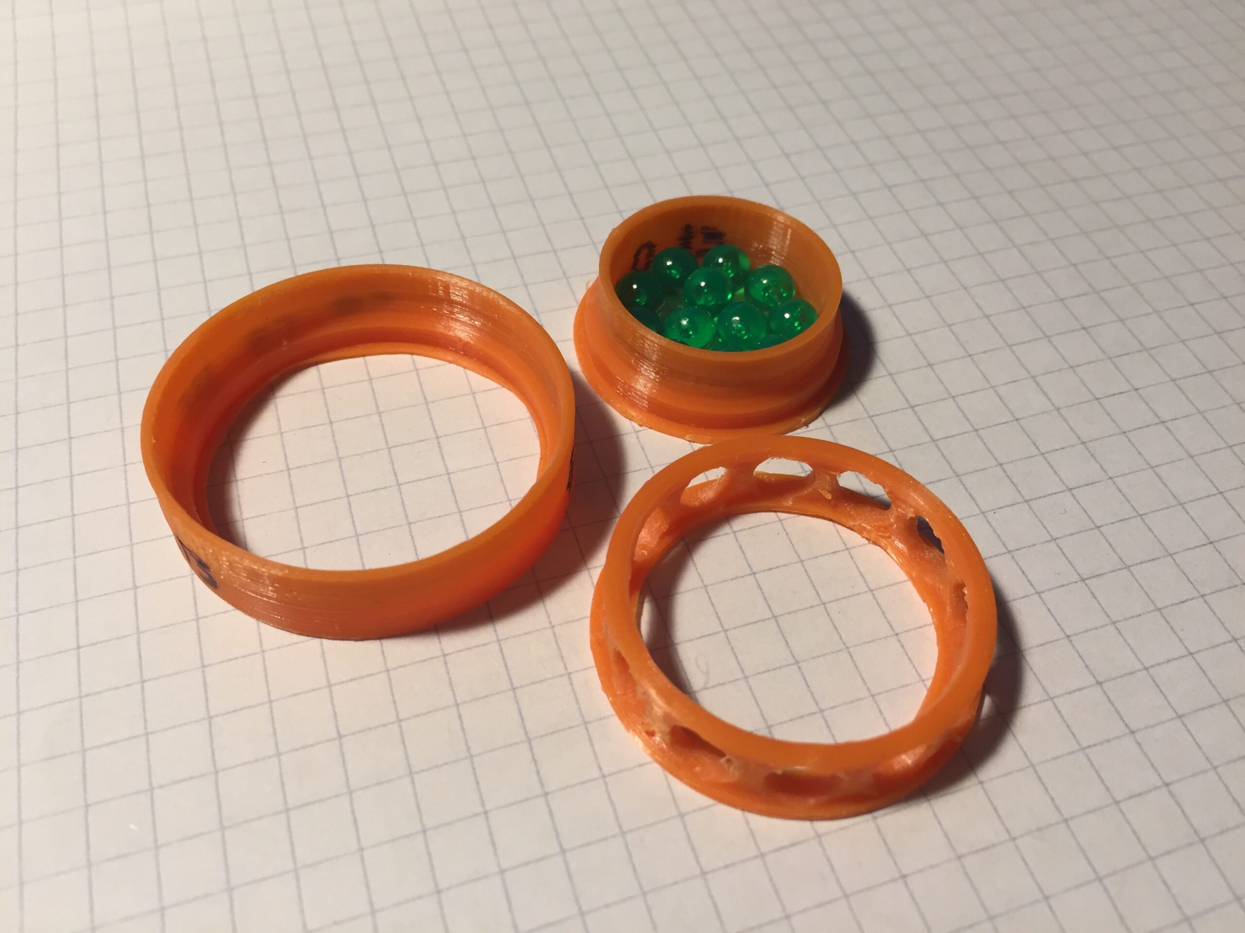
All in one night of boredom, I continually designed and printed about half a dozen different ball bearings of various types. All of these images were taken using .20″ grid paper as a background for scale. The following are the result:

PB01 was an experiment in the amount of clearance the races would need in order to allow the balls to roll smoothly. In the end, the races were too loose and the balls had a tendency to work their way out from between the races when the semicircular cut-outs I used to insert them were aligned.
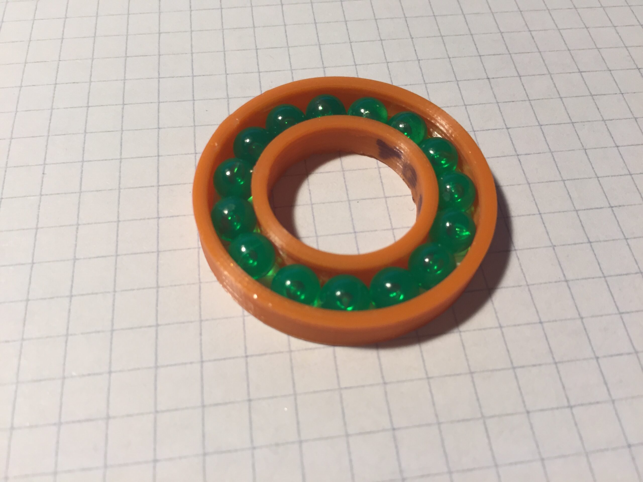
PB02 was an experiment in supporting the rotating shaft with the balls directly and replacing the inner race with a spacer ring. Assembly of the bearing was exceptionally difficult as the bearing had a remarkable propensity for rapidly disassembling itself. The inner diameter of the ball clearance was almost perfectly sized to use a Pilot G2 pen for a shaft. However, when I tested the bearing on this surface, I found that the ball simply slid around the pen’s smooth surface. In modifying the outer race to maintain a better hold of the balls, it seemed that I had slightly undersized the race radius, resulting in the balls binding in the bearing. The idea might still have some merit, but I had already moved on by the time I found all of this out.
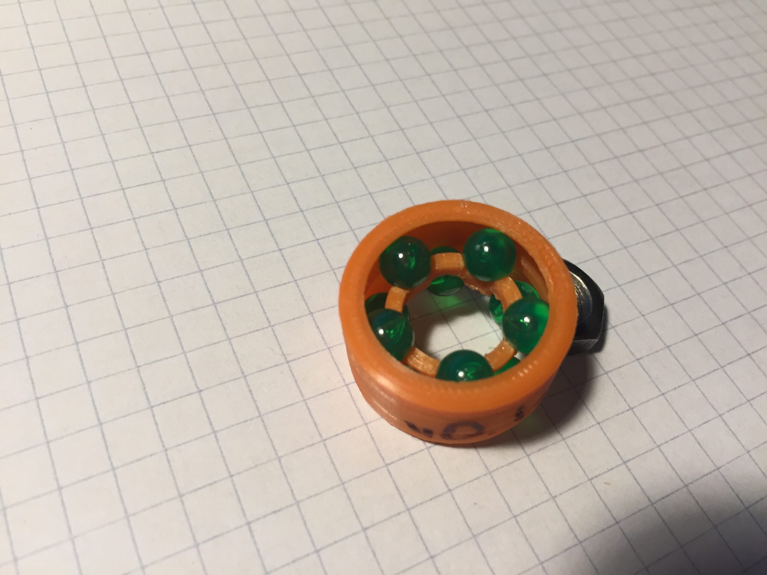
PB03 was intended to figure out how thick race walls should be in order to still allow the deformation necessary to press the balls into place. I wanted to be able to insert them one at a time and so I omitted the spacer. The races for this bearing were looser that those of PB02 but tighter than PB01, resulting in comparatively little resistance. The shallow races made balls easy to insert but also meant that applying even a little torque to a shaft could cause the balls to escape. It was a step in the right direction, not the final product.
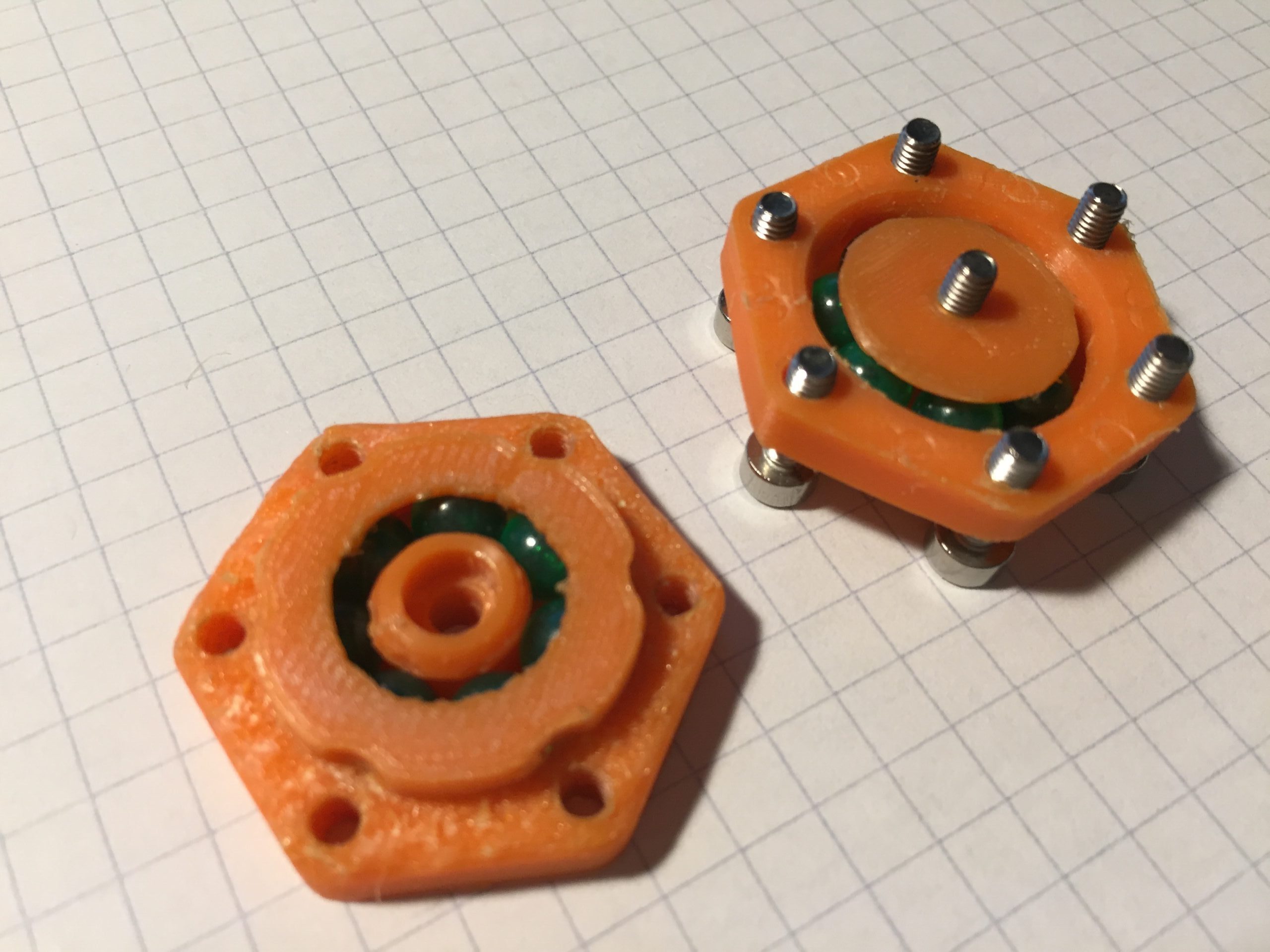
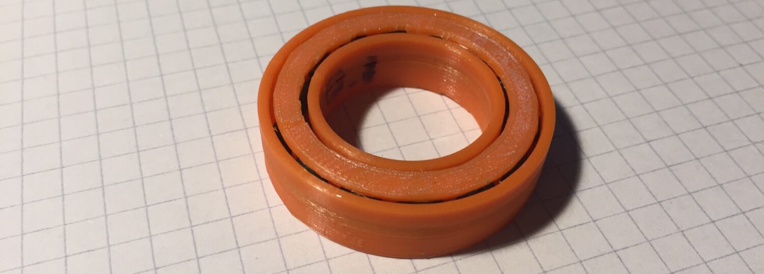
PB04 was perhaps an over-reaction to the seeming fragility of my earlier designs. It was designed as a double-row angular contact bearing which would be pressed together and held with the help of six M3 screws around the races. Sturdy it was and the force produced by screws was great enough to permanently deform the outer race wall of the inner race when the balls were pressed into place. In hindsight, it is surprising that the PLA threads in the screw holes held up while the race wall was being reformed. If you look close enough at the image, you can see where this occurred. The bearing itself was seemingly indestructible but alas, the parts had lost around .005″ at the top of the print, meaning that the two halves were being held together by the screws, against the balls. This was confirmed when I loosened the screws and the bearing spun more freely. Below is a clip of me spinning the bearing after loosening the screws.

PB05 was a return to convention, taking all of the lessons learned from the previous prototypes. The race walls were brought within 1mm on the bottom of the bearing while remaining open at the top to allow the balls to be pressed into place. A spacer was included to keep the balls from binding on one other and featured an integrated shield on the top to cover the otherwise open top of the bearing. The design was solid and functioned ok, but the initial print was rather tight and required some persuasion to rotate. After several more modifications and test prints, I arrived at a design which spun easily enough to be called a proper bearing. At last, I had succeeded where three years prior I had fallen short: a functional, 3d printed ball bearing.

For now, that is the extent of my brief adventure in printing bearings. In the future, I would like to investigate the lifespan and performance of improved PB05 bearings in order to better understand how and why they might be used in practical applications. However, it would be silly if all I knew about was ball bearings, so I hope to bring periodic updates on a myriad of other projects I am working on.
Until next time,
Austin Wells