
Penknife Multi-tool 3D Model
As a final project for my “Foundations of Graphics” course (GC 120), students were required to select a multi-part object which they would then measure and model in SolidWorks, create CAD drawings of 5 parts, a technical sketch of a ‘difficult part’, and an assembly drawing. For this project, I selected a generic brand penknife multi-tool which I had retired years ago. The instructor recommended that our object have between 5 and 8 parts; this knife, however, was composed of around 50 parts. Below are the deliverable components of this project.

Title page with rendering of assembly model

Assembly exploded-view and normal isometric of the knife
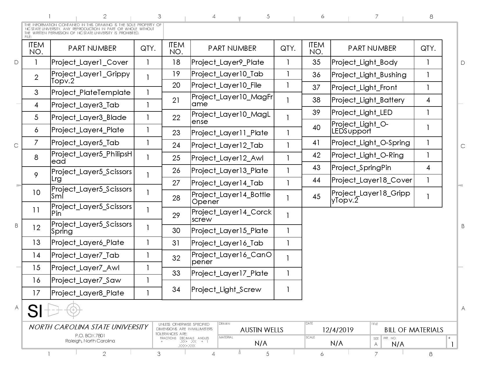
Bill of materials refered to in the exploded-view assembly drawing
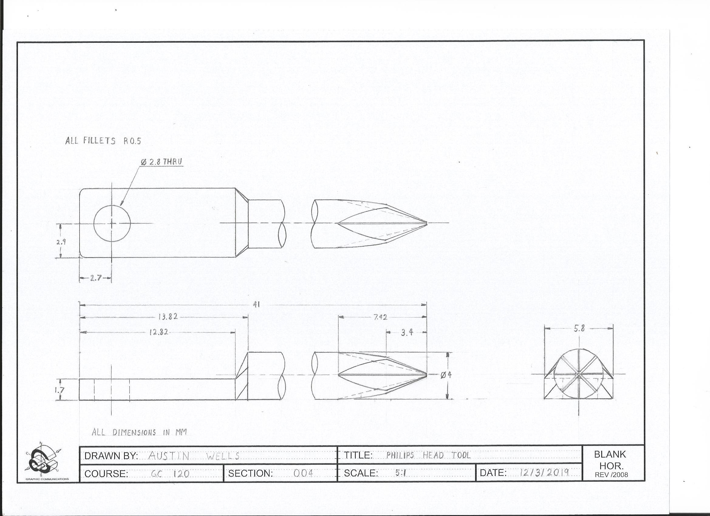
Technical sketch of the phillips head screw driver tool from layer 5 of the knife (hand drafted)

Drawing of the lens of the knife’s flashlight
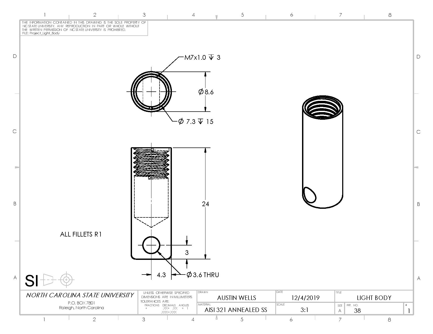
Drawing of the main housing of the knife’s flashlight

Drawing of the spacing plate between layers 7 and 9 of the knife
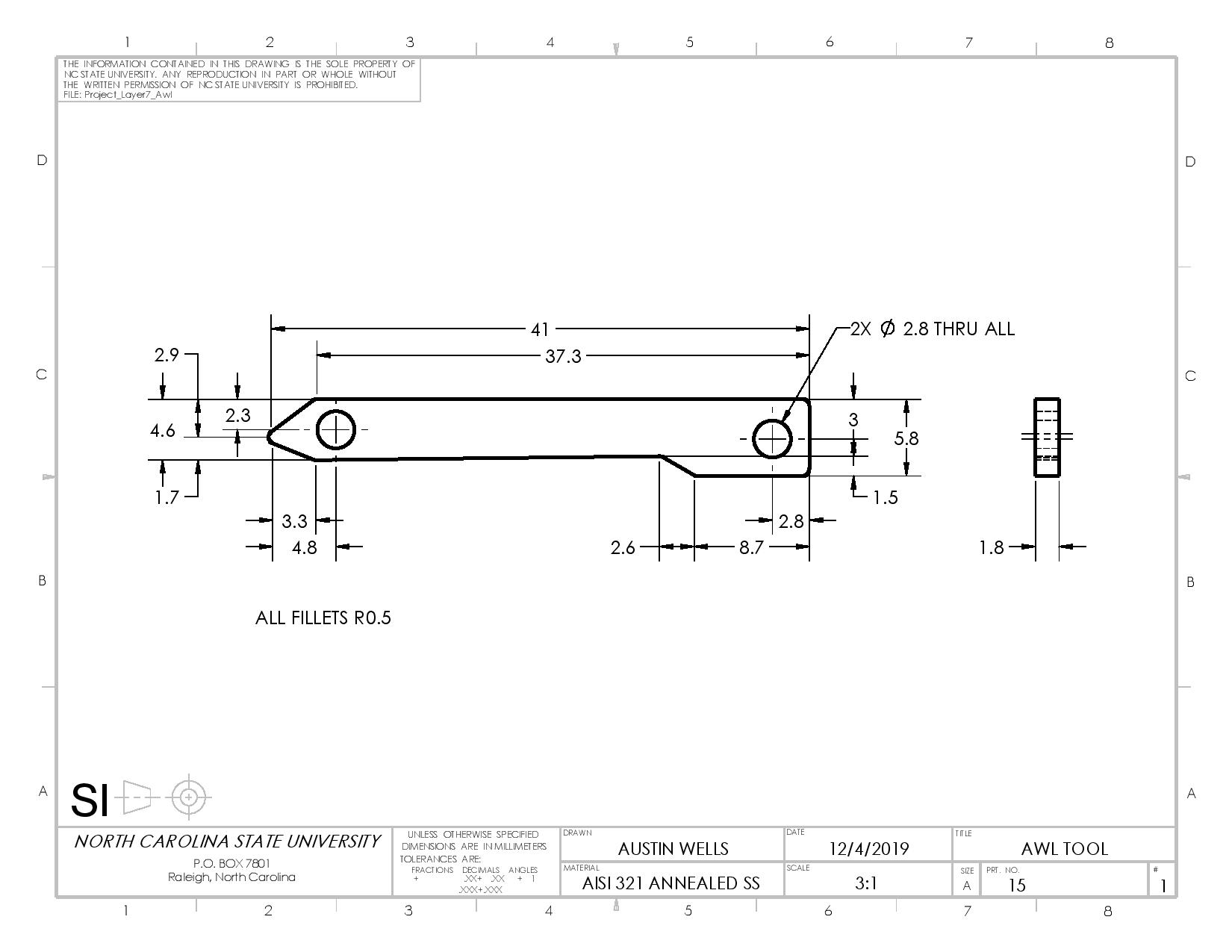
Drawing of the awl tool from layer 7 of the knife
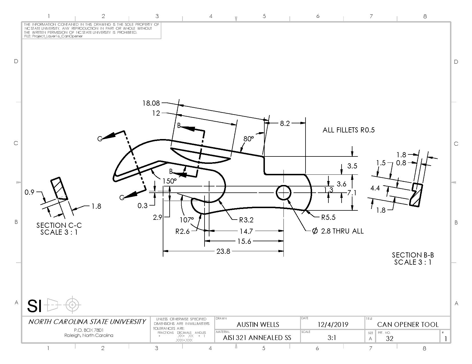
Drawing of the can opener from layer 16 of the knife